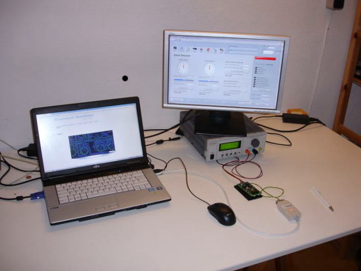
Aufgabenstellung der Projektarbeit bestand darin eine kleine Elektronik mittels CAN Bus zu Steuern und die Speicherwerte zu visualisieren. Hardwareseitig kam dafür ein PCAN CAN – USB Adapter zum Einsatz. Die Programmierung der Software wurde auf einem Standard Windows 7 Laptop mit installiertem National Instruments LabView 2010 ausgeführt. Als zusätzliche Anforderung sollte die Software als Executable kompiliert und in einen Windows Installer verpackt werden.
There was a question for a little project to control and visualize a electronic device via CAN Bus. The connection between PC and electronic device was established via a PCAN CAN USB Adapter. The developement of the software was done on a standard Windows 7 Laptop with National Instruments LabView 2010 installed. As an additional requirement the final software should be compiled as an executable an packed into a Windows Installer.
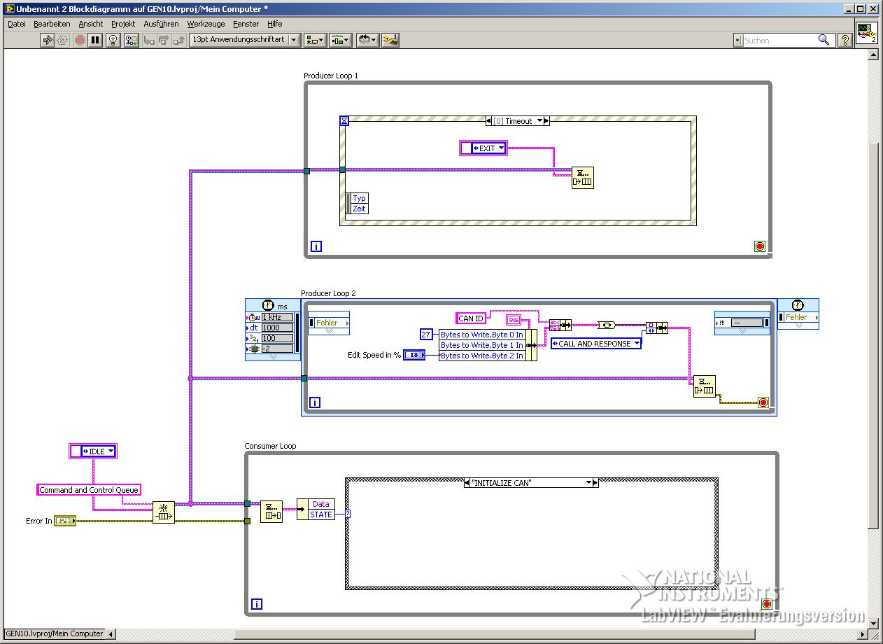
Basic Program Architecture: Event Driven Queued State Machine
Der Grundaufbau des Testprogrammes besteht aus einer sogenannten Producer-Consumer-Architektur. Die Grundidee dieser Struktur ist der Datenaustausch zwischen verschiedenen Programmschleifen die in individuellen Takten ausgeführt werden. Damit ist es möglich das „Erzeugen“ und das „Verbrauchen“ von Daten programmatisch zu trennen. Um Daten zwischen den parallel laufenden Programmschleifen auszutauschen, wird auf sog. Daten-Queues zugegriffen. Diese Datenqueues bieten den Vorteil eines gepufferten Datenaustausches zwischen parallel laufenden Prozessen.Diese Grundarchitektur wird im Fall des Testprogrammes erweitert zu einer sog. Event Driven Queued State Machine. Dabei beinhaltet die Consumer Loop zusätzlich eine State Machine. Durch die Verbindung mittels der Queue kann nun von der Producer Schleife bei konkreten Programmereignissen ein Zustand an die Consumer Loop übermittelt werden, welcher dort von der State Machine abgearbeitet wird. Des Weiteren wird in der Queue nicht nur der abzuarbeitende Zustand, sondern auch weitere Daten von der Producer- in die Consumer Schleife transferiert. Dies ist möglich, in dem der Datentyp der Queue als Cluster der beiden Elemente „Zustand“ und „Daten“ definiert ist. Während das Element „Zustand“ vom Datentyp Integer die State Machine steuert, transferiert das Element „Daten“ vom Datentyp Variant beliebige Daten in die State Machine. Detaillierte Informationen zu dieser fortgeschrittenen LabView Architektur können auf der Homepage von National Instruments hier gefunden werden.
The basic architecture of the test programm is realized as a so called Producer-Consumer-Architecture. The main advantage of this programm structure is the data exchange between the particular loops while each loop is executed with an individual cycle time. Therefore it is possible to separate the producing and the consuming of data programmatically. To realize the data exchange between parallel executed loops LabView offers so called Data-Queues. The big advantage of this Data-Queues is the buffered data exchange between parallel executed tasks.This basic architecture is extended to a so called Event Driven Queued State Machine. By doing so there is a classic state machine added to the consumer loop. Through the connection of the data queue the producer loop is able to call the execution of particular states of the state machine and additionally submit individual data to this state. This is possible because the data type of the data queue is defined as cluster of the integer element „state“ and the element „data“, which is defined as variant. While the element „state“ is controlling the state machine, the element „data“ transfers arbitrary data to this desired state. Further information to this advanced LabView architecture can be found on the National Instruments homepage here


Program Functionality
Grundlegend wird das Testprogramm mittels eines Windows Installers auf einem beliebigen Windows XP oder Windows 7 Rechner lauffähig installiert. Bei erfolgreicher Installation kann über eine graphische Benutzeroberfläche die Interaktion zwischen Bediener und Elektronik erfolgen. Das Programm enthält diverse zentrale Funktionalitäten zum Ansteuern und Auslesen der Elektronik mittels CAN Bus. Die wichtigsten davon sind:
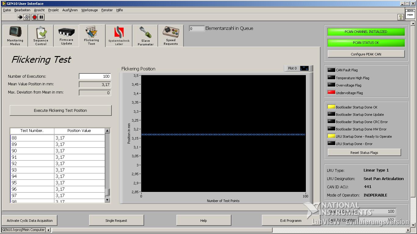
- In einem sog. Testing Modus können mit einem Takt von 100ms wichtige elektronische Parameter und Sensordaten angezeigt und visualisiert werden
- Ein Sequencer ermöglicht dem Benutzer mittels Excel Dateien eine Sequenzfolge zu erstellen, welche vom Programm abgearbeitet wird. Somit ist es möglich Abfolgen von CAN Nachrichten und Strukturen wie JUMP oder WAIT zu kombinieren und individuelle Prüfsequenzen zu erzeugen.
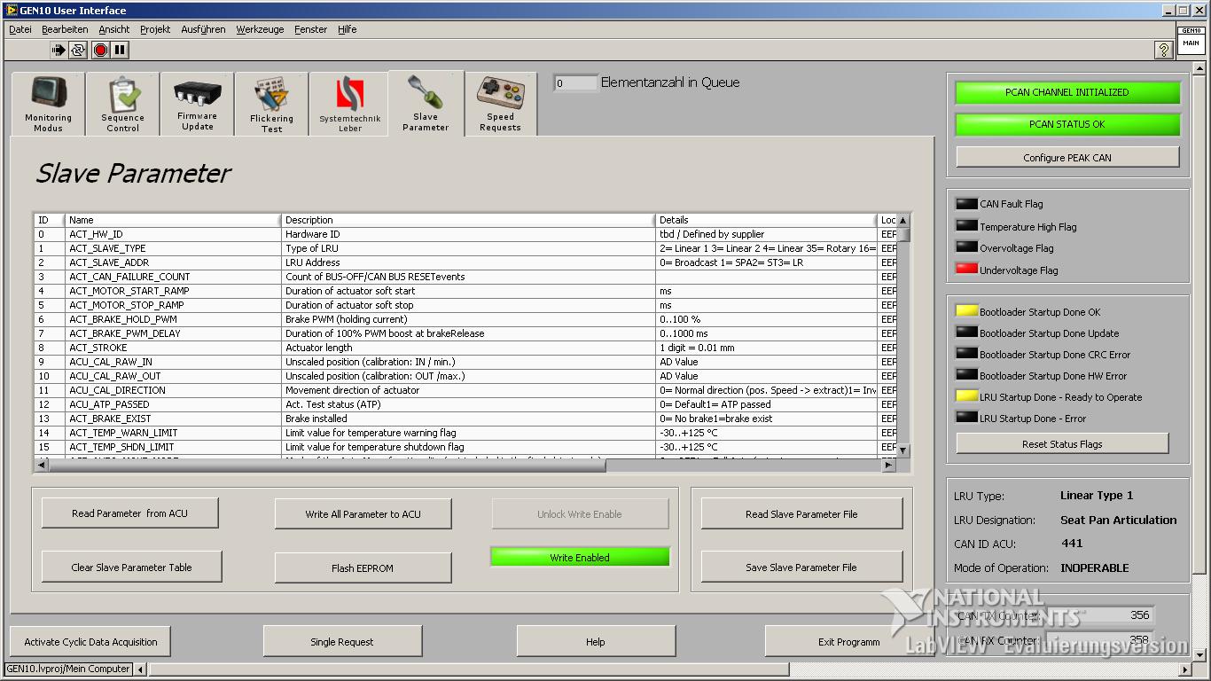
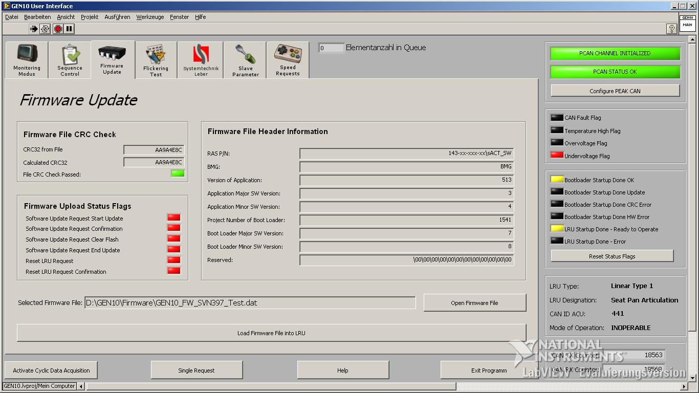
- Das Ausführen von Firmware Updates ermöglicht das Aktualisieren der elementaren Mikrocontroller Software. Die dafür benötigten binären Herstellerdateien werden interpretiert, aufbereitet und über ein definiertes Protokoll in die Elektronik eingespielt.
- Das EEPROM der Elektronik kann ausgelesen und der Inhalt in Klartext mit Erläuterung dargestellt werden. Die Daten können verändert und dauerhaft durch ein Flashen des EEPROM gesichert werden.
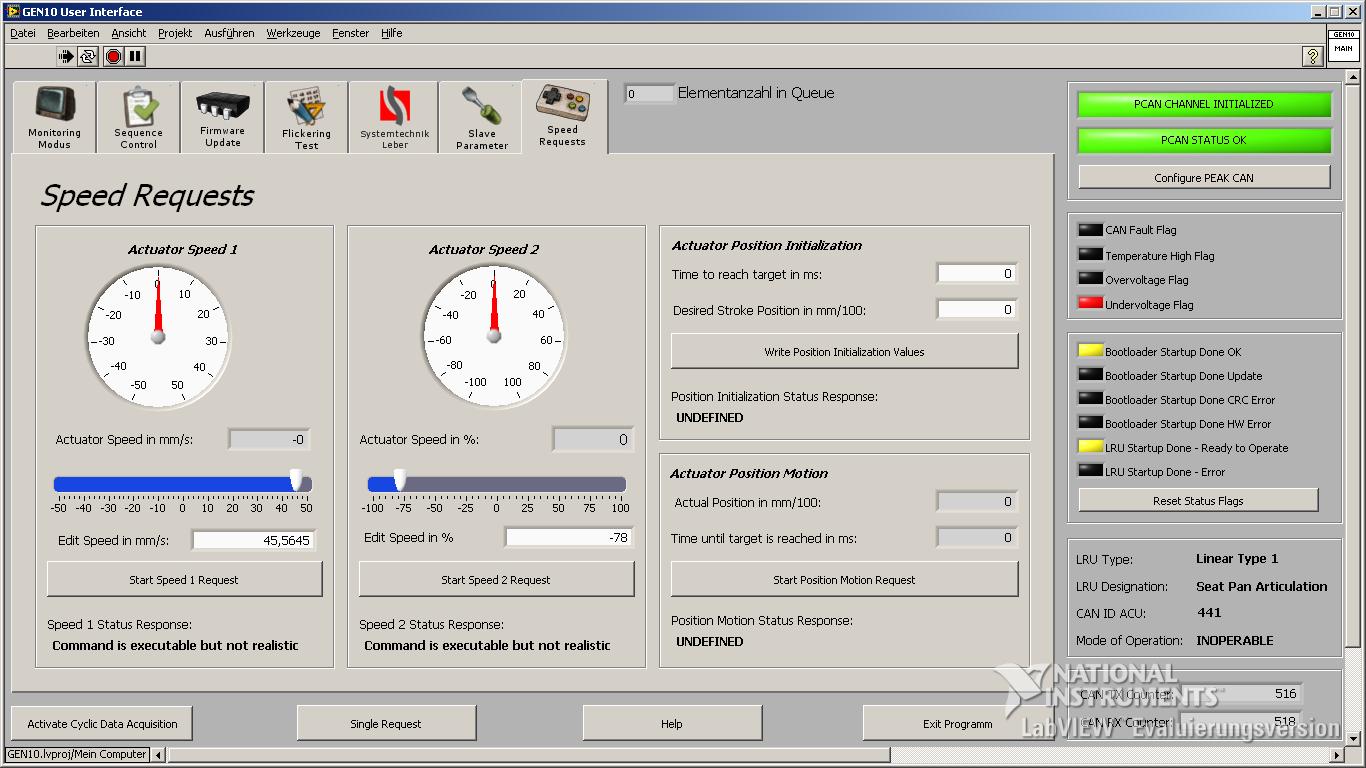
- Da die Elektronik unter anderem als Ansteuerung für einen Elektromotor dient, ist es möglich verschiedene Fahrbefehle für die Antriebskomponente zu versenden und den aktuellen Status (Geschwindigkeit, Position, etc.) darzustellen
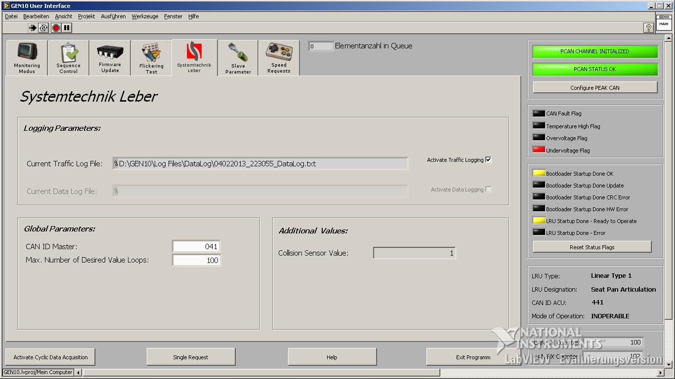
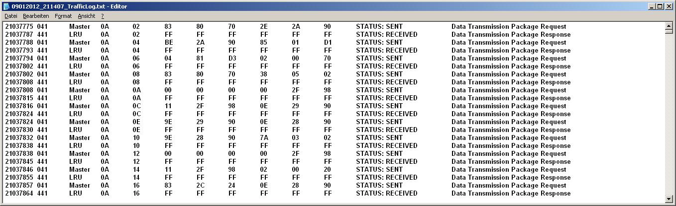
- Eine detaillierte Logging Funktionalität ermöglicht sowohl das sichern des gesamten CAN Bus Traffic, aller aufgetretenen Fehler und Warnungen sowie optional ein Datenlogging per relevanter Daten als *.csv Datei
Basically the test program can be installed with a windows installer on any Windows XP or Windows 7 machine. After a successful installation the user can interact with the electronic device over an graphical user interface. The program contains several main functionalities to control and visualize electronic parameters of the device under test. The communication is based on CAN Bus. The most important functions are:
- In Testing Mode several electronic parameters and sensor values can be displayed as text and graphical view
- The sequence control mode enables the user to execute sequences. The sequences are made with Microsoft Excel. Within this sequences it is possible to combine CAN commandos and structures like JUMP, WAIT and others. So the user is able to create mighty test sequences.
- The Firmware Update Mode enables the user to update the fundamental software, which is running within the microcontroller of the electronic device. The necessary binary manufacturer files are interpreted and sent over a defined protocol to the microcontroller.
- An EEPROM dump can be performed and the content can be displayed in readable format. Furthermore the content can be changed and overwritten. The opportunity to flash the EEPROM enables the user to save the changed content permanently.
- The main purpose of the test electronic is drive controlling. Therefore it is possible to send miscellaneous drive commands to the electronic and display the current status of the motor (speed, position, etc.)
- A detailled logging functionality allows the logging of the complete CAN Bus traffic, all occured errors and warnings and optionally a data logging of relevant data as *.csv file.
Schreibe einen Kommentar